Connecting a JK BMS
Overview
This guide is for the original JK BMS. See our JK inverter BMS guide if you have their newer "JK PB" BMS range.
Step 1 - Connections and components
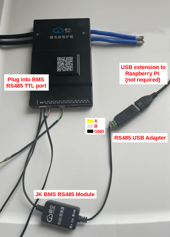
The typical setup requires the two components below. We do not sell any of them.
- JK BMS RS485 module
- USB RS485 adapter (ensure it's not TTL). We recommend FTDI chip adapters.
Note you can also use a USB TTL adapter instead of the two adapters above, but it requires manual wiring into the JK BMS where the JK BMS RS485 module connects.
Step 2 - Configure SolarAssistant to connect to a JK BMS
On the SolarAssistant configuration page, select the protocol below.
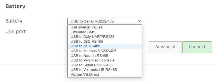
Select one or more USB cables and click connect:
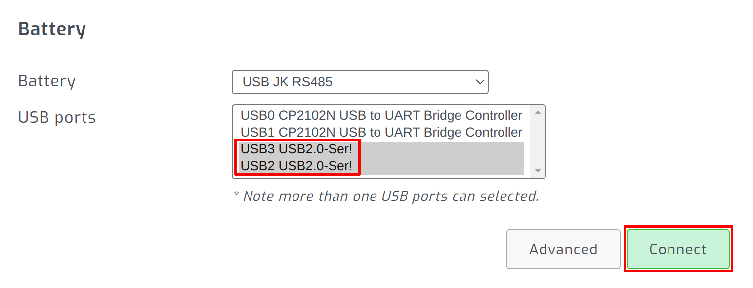
Plug the RS485 USB cable into the SolarAssistant monitoring device. Once you click "connect" on the configuration page, you should see each BMS show up as a battery pack as shown below.
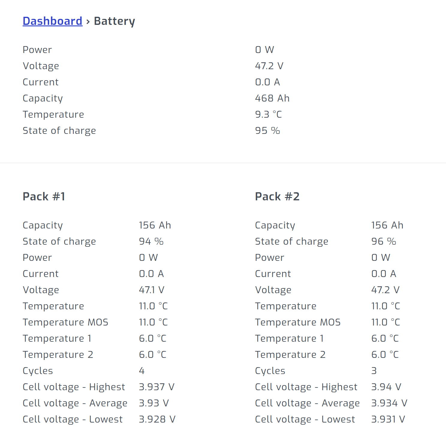
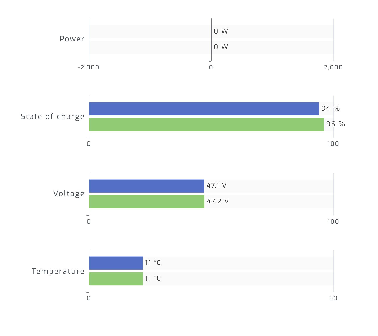
Result
One pack will be shown for each JK BMS connected in step 2 above.