SC16IS752 dual UART expansion
NB: For most users, we recommend using USB cables to connect inverters and batteries. This article is for advanced users who connect via PCB boards wired to the Raspberry Pi header pins.
Different Raspberry Pi models have different numbers of UART ports available on the header pins:
| Raspberry Pi Model | Header UART Ports |
|
Raspberry Pi Zero Raspberry Pi Zero W Raspberry Pi Zero 2 W | 1 |
| Raspberry Pi 3 | 2 |
| Raspberry Pi 4 | 2 |
| Raspberry Pi 5 | 2 |
Note: The Raspberry Pi Zero 2 W has a second UART, but it is not available on the header pins. It requires soldering the RPi board and disabling Bluetooth.
This guide explains how to use the SC16IS752 to add 2 additional UART ports to any Raspberry Pi.
Hardware options:
- SC16IS752 breakout board - requires wiring to the Raspberry Pi header pins
- Waveshare Serial Expansion HAT - a plug-and-play HAT that connects directly to the Raspberry Pi GPIO header
Step 1: Wiring
If you purchased the Waveshare HAT, you can skip this step as it plugs directly onto the Raspberry Pi header.
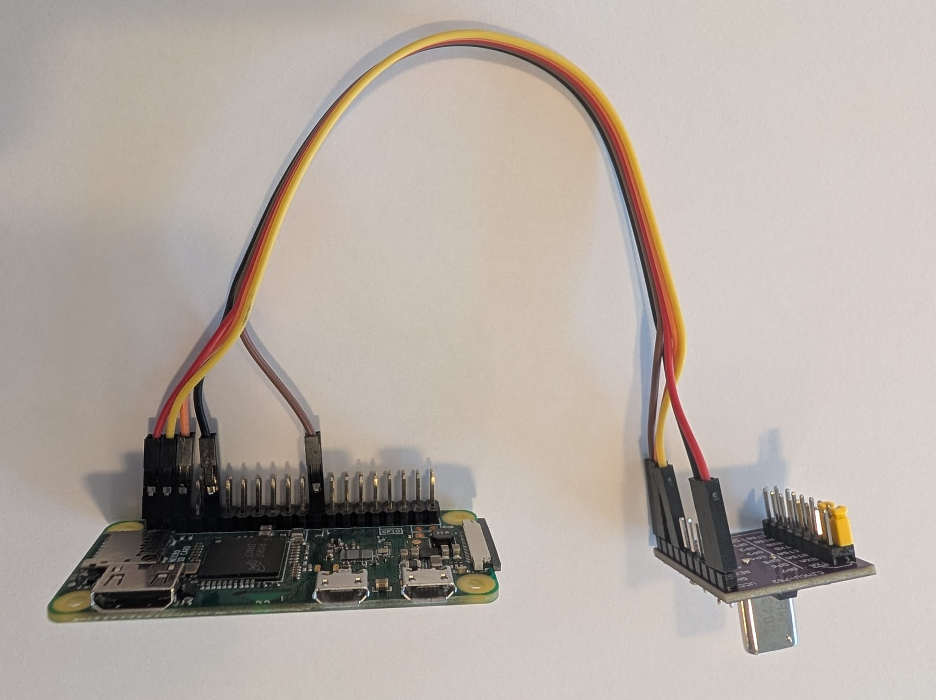
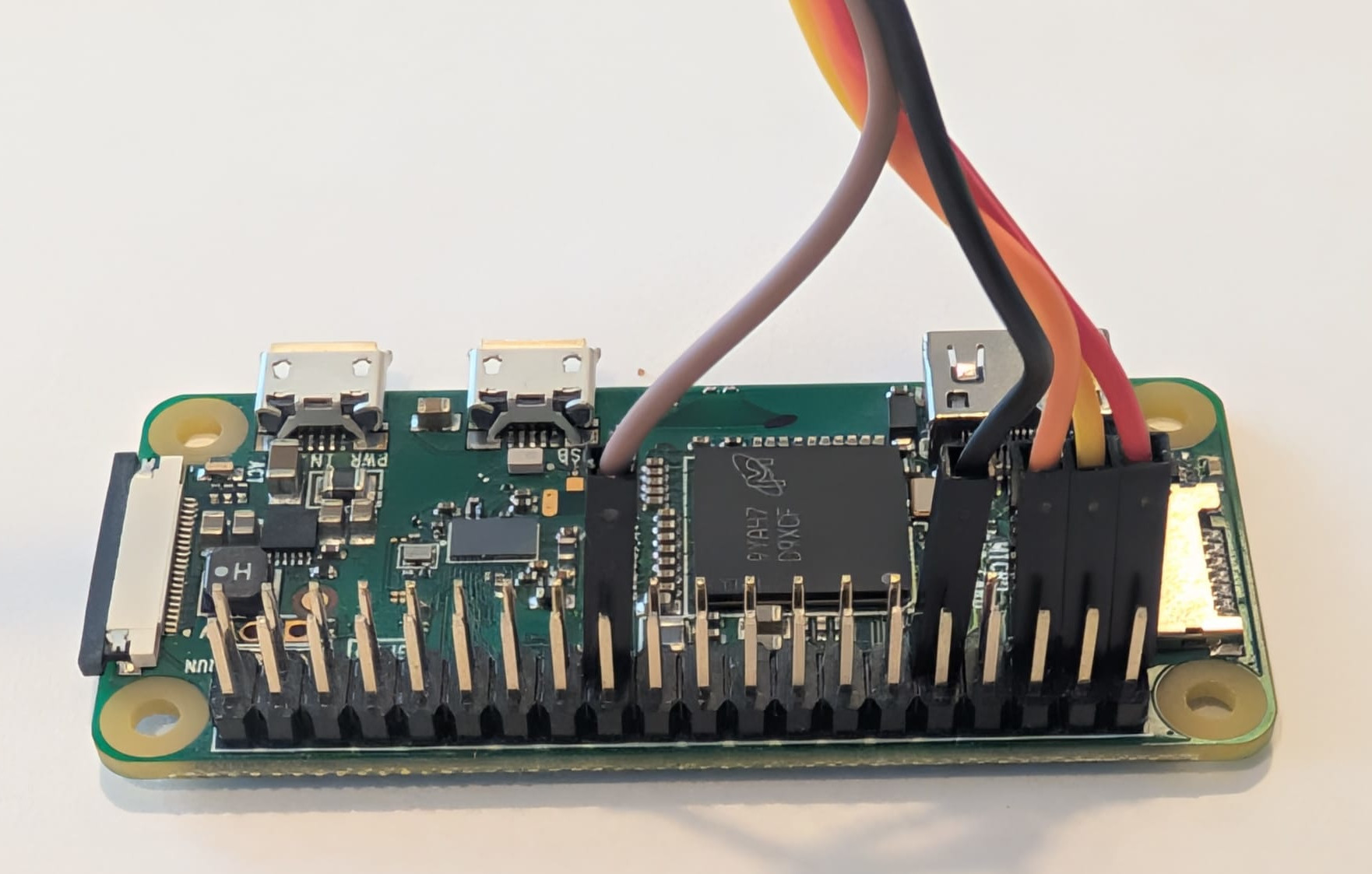
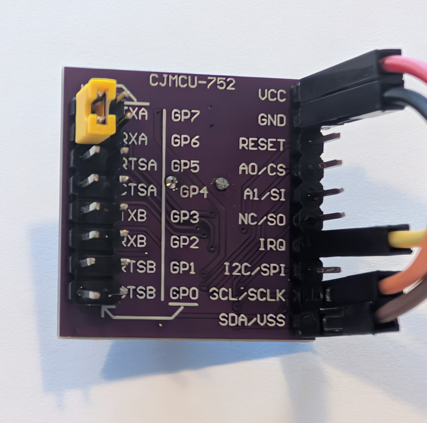
Connect the SC16IS752 breakout board to the Raspberry Pi header pins as follows:
| RPi pin number | RPi pin name | SC16IS752 pin |
| 1 | 3.3V Power | VCC |
| 6 | Ground | GND |
| 3 | SDA (I2C Data) | SDA |
| 5 | SCL (I2C Clock) | SCL |
| 11 | GPIO 17 | IRQ |
Step 2: Connect via SSH
Connect to your SolarAssistant device via SSH. See the SSH access guide for instructions on enabling and connecting via SSH.
Step 3: Enable I2C and configure the device tree overlay
Edit the boot configuration file:
sudo nano /boot/firmware/config.txtAppend the following lines to enable I2C and the SC16IS752 overlay:
dtparam=i2c_arm=on
dtoverlay=sc16is752-i2c,addr=0x4d,int_pin=17
If your board uses a 1.8432 MHz crystal instead of the standard 14.7456 MHz crystal, add the
xtal parameter:
dtoverlay=sc16is752-i2c,addr=0x4d,int_pin=17,xtal=1843200Save the file and reboot the Raspberry Pi for the changes to take effect.
Step 4: Verify the SC16IS752 board is detected
Install I2C tools and scan the I2C bus:
sudo apt update
sudo apt install -y i2c-tools
sudo i2cdetect -y 1
If the SC16IS752 board is connected correctly, you should see output similar to:
     7  8  9  a  b  c  d  e  f
00:    -- -- -- -- -- -- -- --
10: -- -- -- -- -- -- -- -- --
20: -- -- -- -- -- -- -- -- --
30: -- -- -- -- -- -- -- -- --
40: -- -- -- -- -- -- 4d -- --
50: -- -- -- -- -- -- -- -- --
60: -- -- -- -- -- -- -- -- --
70: -- -- -- -- -- --
The 4d at address 0x4d indicates the SC16IS752 board is detected and working. If you see all dashes, check your wiring connections. Verify that the detected address matches the addr value configured in Step 3.
Step 5: Verify the UART ports are available
Check that the kernel has recognized the SC16IS752 and created the UART devices:
dmesg | grep -i sc16You should see output similar to:
1-004d: ttySC0 at I/O 0x0 (irq = 160, base_baud = 921600) is a SC16IS752
1-004d: ttySC1 at I/O 0x1 (irq = 160, base_baud = 921600) is a SC16IS752
Verify that the serial devices exist:
ls -l /dev/ttySC*Expected output:
crw-rw---- 1 root dialout 240, 0 Feb 4 20:56 /dev/ttySC0
crw-rw---- 1 root dialout 240, 1 Feb 4 20:56 /dev/ttySC1
Step 6: Test the UART ports
To test that the UART ports are working, connect TXA and RXA together on the SC16IS752 board (loopback test). Note the yellow jumper wire in the wiring images above as an example.
In one terminal, listen for incoming data:
sudo cat /dev/ttySC0In another terminal, send data:
echo -n "hello" > /dev/ttySC0If the ports are working correctly, you should see "hello" appear in the first terminal.
Step 7: Configure in SolarAssistant
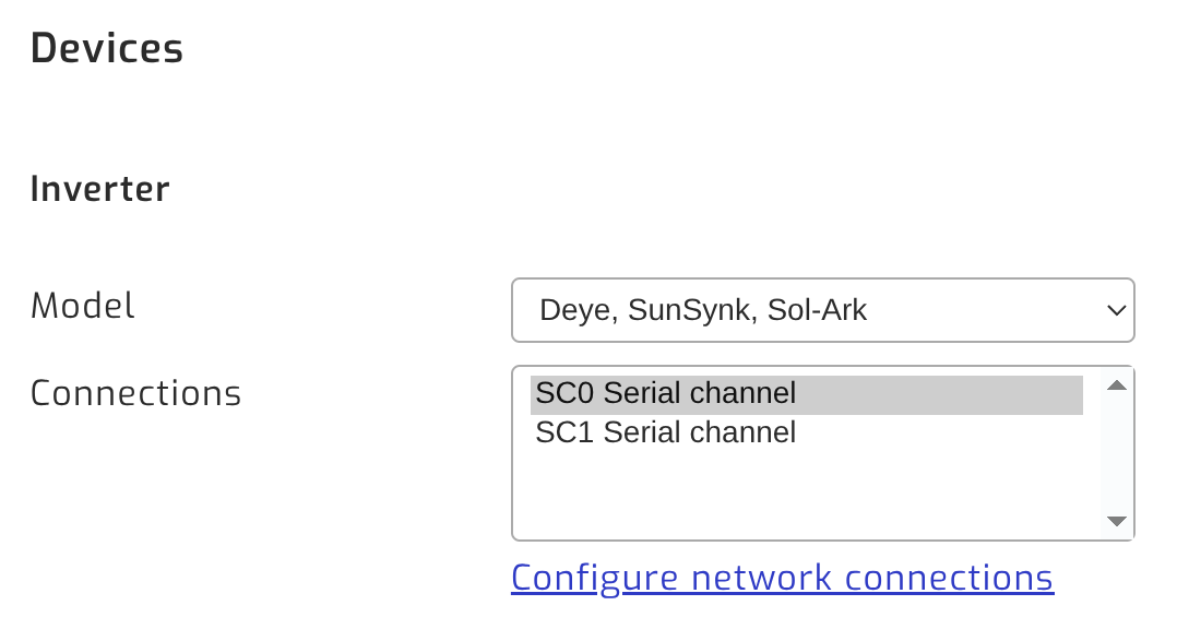
The new UART ports will appear in SolarAssistant as "SC0 Serial channel" and "SC1 Serial channel" when selecting the connection port for your inverter or battery.