RS485 port
When it comes to these inverters, you will need an SRNE RS485 cable using the RJ45 pin configuration below:
| Pin 1 | - |
| Pin 2 | - |
| Pin 3 | - |
| Pin 4 | - |
| Pin 5 | - |
| Pin 6 | - |
| Pin 7 | RS485A |
| Pin 8 | RS485B |
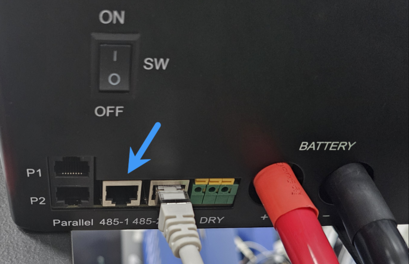
You can then plug that cable into the "485-1" port on the inverter, as shown below:
If you buy any random USB RS485 RJ45 cable on Amazon, Ebay, Takealot, etc. which doesn't specifically state that it supports the inverter, it will most likely not work. You can read more about the communication chips we recommend using here.
Steps in SolarAssistant
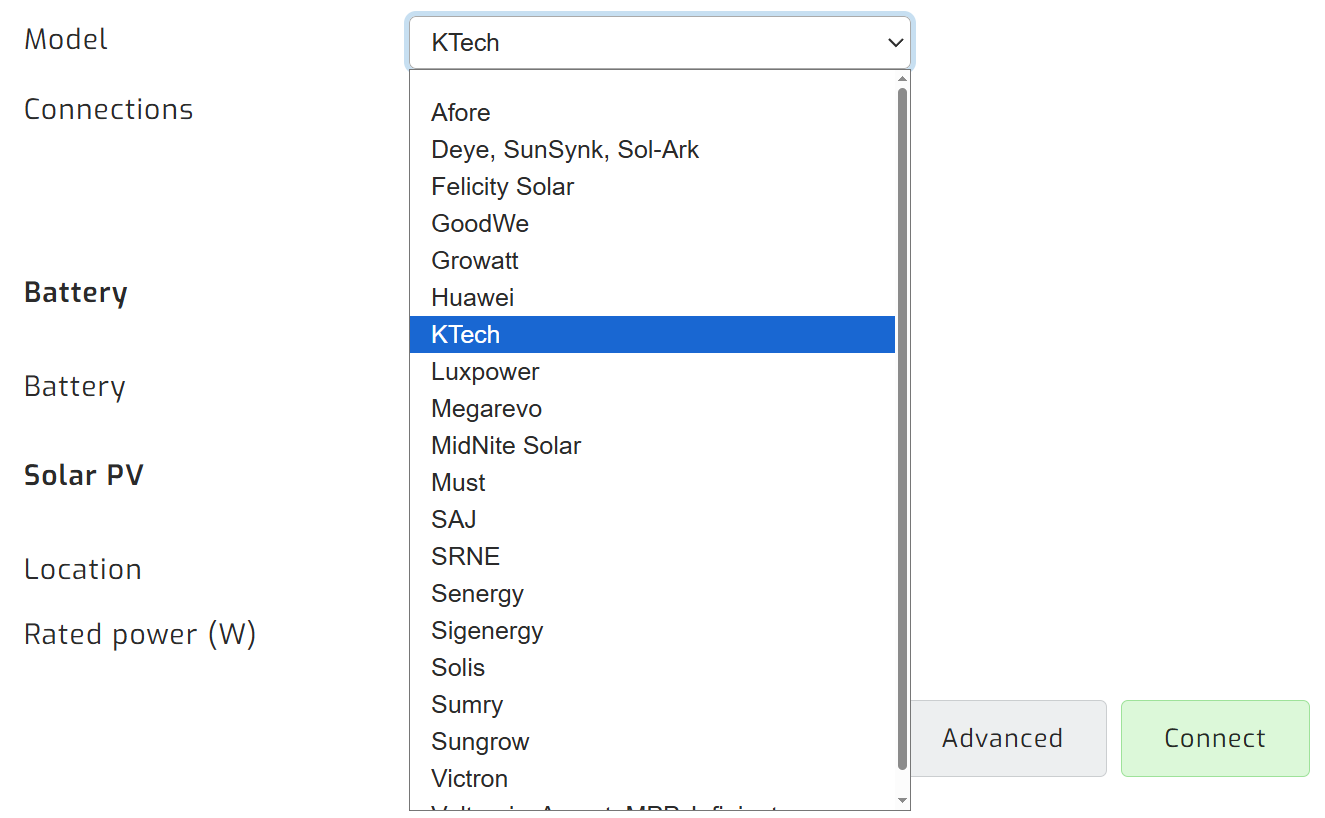
On the configuration page, select "KTech" as your inverter model.
Select the USB port(s) where you have inverters connected. There will typically be one option.
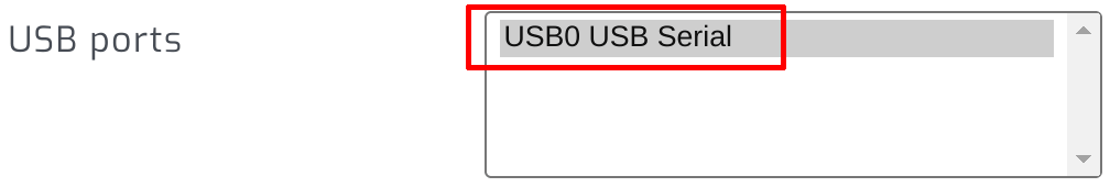
Click connect:
Parallel installations
With these inverters you will need to connect each inverter with its own cable.
Troubleshooting
Inverter RS485-1 communication settingsIf SolarAssistant is unable to connect to your inverter, please verify the RS485-1 communication settings on your inverter's LCD screen. This can be found under Settings, then Communication settings and then RS485-1 settings. If you are unable to locate these settings, please refer to your inverter's user manual for further guidance.
| Setting | Value |
| RS485 work mode | Modbus-slave |
| RS485 communication baud rate | 9600 |
| RS485 communication check | None |
| RS485 communication data bit | 8 |
| RS485 communication stop bit | 1 |
Alternative pin configuration
While pins 7 and 8 are the standard configuration, we have seen rare instances where pins 1 and 2 were required instead.
| Pin 1 | RS485B |
| Pin 2 | RS485A |
| Pin 3 | - |
| Pin 4 | - |
| Pin 5 | - |
| Pin 6 | - |
| Pin 7 | - |
| Pin 8 | - |
If you find that pins 1 and 2 work for your inverter, please let our support team know so we can investigate.